Problem
Irrigation is a necessary task when growing crops in areas with low rainfall, as plants often require additional water beyond what natural sources provide. However, manual irrigation can be cumbersome and time-consuming. Automating the irrigation process would be ideal, eliminating the need for individuals to remember the irrigation schedule. A friend approached me with a request to automate their farm's irrigation so that they wouldn't have to be present every time the farm needed watering. The requirements were simple: they wanted to schedule irrigation to start every morning and evening for a specified duration, based on water availability and the moisture content of the plants' roots.
Upon receiving this request, my main task was to determine the best way to solve the problem using the available resources and skills. Since one of the key requirements was the ability to control the irrigation remotely, we needed continuous connectivity to the controller or the ability to manually adjust and maintain settings on the device. The second option was easy to implement since all the information could be stored on the device. However, it lacked versatility since settings could only be adjusted on the device itself, requiring someone to be present to modify the schedule if needed. Additionally, it would be difficult to verify whether the irrigation schedule was executed as intended. Considering all these drawbacks, I decided to implement the second option, where the controller would remain connected to the internet at all times. This decision was also influenced by the fact that the controller would only consume and transmit text-based data, which is lightweight and consumes minimal data.
Technology Selection
With the problem and potential solution outlined, the next step was to select the appropriate devices and software to execute the plan. I considered several microcontrollers, including Arduino, Raspberry Pi, NodeMCU, and ESP32. To make an informed decision, I evaluated each option and eliminated some based on specific criteria.
Arduino boards were disqualified due to their requirement for additional modules to connect to the internet. This increased the installation cost and introduced a potential failure point in the integration. Raspberry Pi, although capable with its built-in Ethernet port, was deemed overkill and expensive for this relatively simple project.
Ultimately, I chose NodeMCU for the following reasons:
- Cost-effective
- Built-in Wi-Fi module
- Compatibility with the Arduino ecosystem
After selecting the microcontroller, the next step was to choose a cloud provider to handle communication between the board and the user. I contemplated developing my own solution or integrating an existing one. However, I opted for an established solution to significantly reduce development time. While I have used various platforms in the past, such as Ubidots and Arduino Cloud, I decided to use Blynk due to its appealing interface, compatibility with multiple devices, and user-friendly onboarding process.
Interface development
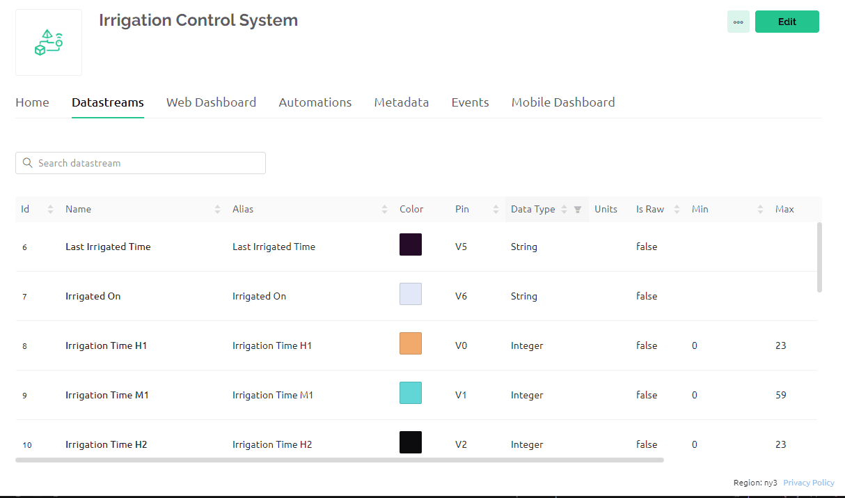
The first step was to create a Blynk account specifically for the project, which was done through the Blynk website. With the account created, the next task was to develop a template that could be utilized on both the mobile and desktop interfaces. Blynk allows the creation of templates that can be shared across multiple devices. These templates were built using a user-friendly drag-and-drop interface. Prior to creating the template, it was necessary to add all the required variables.
Variables serve as the data holders that will be updated when the user inputs data or when the device sends back information.
To create variables, the data stream tab was accessed.
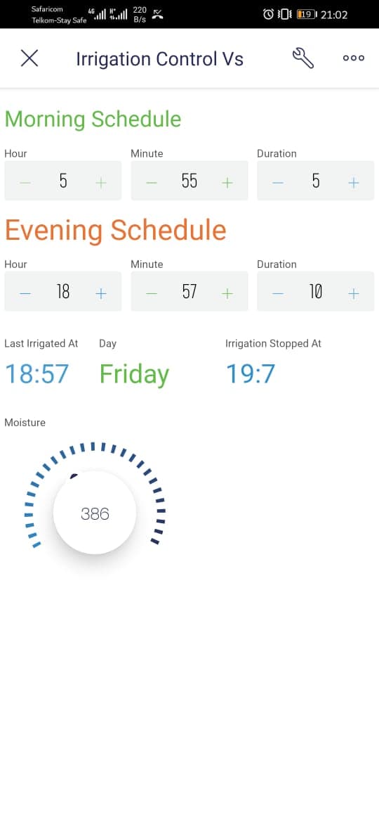
The subsequent step involved adding various components to the web and mobile dashboards.
Please note that the mobile dashboard can only be created on a mobile phone.
My web dashboard is designed with several key features, including sliders for setting the irrigation time, displaying the last irrigation time as a string, indicating when the irrigation stopped, showcasing the moisture level, and presenting a graph illustrating the moisture levels over time.
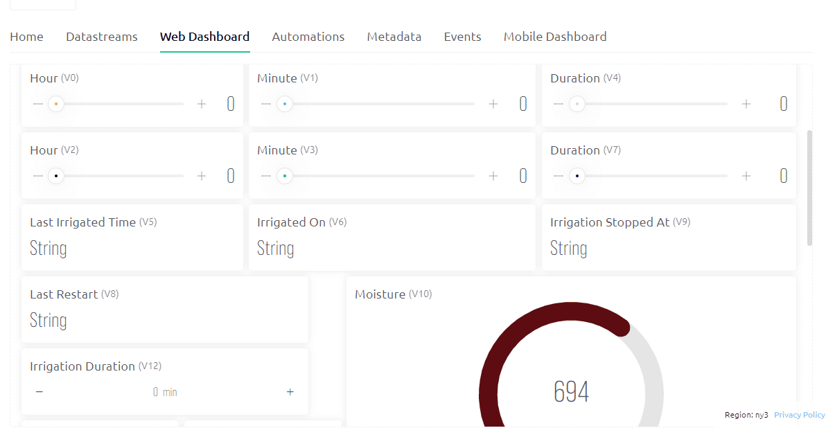
These key elements were deemed sufficient to display the current state of the farm and provide relevant controls for setting and modifying the irrigation time.
Programming
I used arduino c++ to program the controller. I cannot fullt explain the logics of the controller in this article but will explain some key elements of the controller code.
Variables and Libraries
Some of the libraries I used include NTPClient WiFi UDP for wifi connection and obtaining real time from the internet.
Obtaining the real time from the internet was efficient and accurate since I didnt have to add a realtime clock module.
#include <NTPClient.h>
#include <WiFiUdp.h>
#define wifi D7 // This is just a pin to indicate wifi status
//const long utcOffsetInSeconds = 10800;
// Define NTP Client to get time
// This was used to get the east african time from the GMT.
const long utcOffsetInSeconds = 10800;
// Define NTP Client to get time
WiFiUDP ntpUDP;
NTPClient timeClient(ntpUDP, "pool.ntp.org", utcOffsetInSeconds);
#define BLYNK_TEMPLATE_ID "TMPLxxxx-xx" // This can be found on blynk platform
#define BLYNK_TEMPLATE_NAME "Irrigation Control System" // This can be found on blynk platform
#define BLYNK_AUTH_TOKEN "nT6zig8xxxxxxxR2vNpDXR4K5Di1" // This can be found on blynk platform
#define BLYNK_DEVICE_NAME "Irrigation Control System" // This can be found on blynk platform
#define BLYNK_FIRMWARE_VERSION "0.1.3"
// Comment this out to disable prints and save space
//#define BLYNK_PRINT Serial
#include <ESP8266WiFi.h>
#include <BlynkSimpleEsp8266.h>
String phoneNumber = "+254790668724";
char auth[] = BLYNK_AUTH_TOKEN;
char ssid[] = "Router_wifi_name";
char pass[] = "my_secure_password";


BlynkTimer timer;
bool irrigation_started = false;
int irrigation_duration = 30;
int second_duration = 30;
int first_irrigation_start_hour = 10;
int first_irrigation_start_minute = 51;
int second_irrigation_start_hour = 18;
int second_irrigation_start_minute = 30;
int irrigationStopM = 0;
int irrigation2StopM = 0;
int irrigation2StopH = 0;

int pump = D6;
int valve = D5;
int TimeH;
int TimeM;
String DateDay;
char daysOfTheWeek[7][12] = {"Sunday", "Monday", "Tuesday", "Wednesday", "Thursday", "Friday", "Saturday"};
Helper Functions
Most of the auxiliary functions were implemented to guarantee reliable internet connection and connection to the blynk platform. For instance the controllers could periodically check for wifi connection and reconnect whenever a connection is lost. I used the blynk timer method to sync all the processes and the auxiliary functions.
/*
- This module is used to reset the board over the internet
*/
void resetMCU()
{


#if defined(ESP8266) || defined(ESP32)
  ESP.restart();
#else
#error "MCU reset procedure not implemented"
#endif
  for (;;) {}
}
bool realTimeset = false;

BLYNK_WRITE(InternalPinDBG) {
  if (String(param.asStr()) == "reboot") {
    Serial.println("Rebooting...");

    // TODO: Perform any neccessary preparation here,
    // i.e. turn off peripherals, write state to EEPROM, etc.

    // NOTE: You may need to defer a reboot,
    // if device is in process of some critical operation.

    resetMCU();
  }
}

/*
- This module ensures that the time keeps running even if we loose internet connection.
*/

void timeKeeper() {
  if (WiFi.status() == WL_CONNECTED) {
    timeClient.update();
    TimeH = timeClient.getHours();
    TimeM = timeClient.getMinutes();
    DateDay = daysOfTheWeek[timeClient.getDay()];
    realTimeset = true;
    Serial.println("Time set from internet" + String(TimeH) + ":" + String(TimeM));
    Blynk.virtualWrite(V11, String(TimeH) + ":" + String(TimeM));
  }
  else {
    TimeM++;
    if (TimeM > 59) {
      TimeH++;
      TimeM = 0;
      if (TimeH > 23) {
        TimeH = 0;

      }
    }
  }

}

/*
- This module is used check internet connection and send moisture back to blynk
*/

void myTimerEvent()
{
  if (WiFi.status() != WL_CONNECTED) {
    WiFi.disconnect();
    WiFi.reconnect();
if (WiFi.status() == WL_CONNECTED) {
      digitalWrite(wifi, HIGH);
      Serial.print("Connected");
      Blynk.config(auth);  // in place of Blynk.begin(auth, ssid, pass);
      Blynk.connect(3333);  // timeout set to 10 seconds and then continue without Blynk
      timeClient.begin();
      timeClient.update();
      TimeH = timeClient.getHours();
      TimeM = timeClient.getMinutes();
      DateDay = daysOfTheWeek[timeClient.getDay()];
      realTimeset = true;
      while (Blynk.connect() == false) {
        // Wait until connected
      }
      Serial.println("Connected to Blynk server");

    }
    else {
      digitalWrite(wifi, HIGH);
      delay(500);
      digitalWrite(wifi, LOW);
      Serial.print(".");

    }


  }
  checkTime();
  sendMoisture();
  delay(50);
}
Setup Functions
void setup ()
{ delay(100);
  Serial.begin(9600); // Set serial port speed
  WiFi.begin(ssid, pass);
  //WiFi.begin(ssid, pass);
  pinMode(wifi, OUTPUT);
  for (int i = 0; i < 30; i++)  {
    if (WiFi.status() == WL_CONNECTED) {
      digitalWrite(wifi, HIGH);
      Serial.print("Connected");
      Blynk.config(auth);  // in place of Blynk.begin(auth, ssid, pass);
      Blynk.connect(3333);  // timeout set to 10 seconds and then continue without Blynk
      timeClient.begin();
      timeClient.update();
      TimeH = timeClient.getHours();
      TimeM = timeClient.getMinutes();
      DateDay = daysOfTheWeek[timeClient.getDay()];
      realTimeset = true;
      while (Blynk.connect() == false) {
        // Wait until connected
      }
      Serial.println("Connected to Blynk server");
      break;
    }
    else {
      digitalWrite(wifi, HIGH);
      delay(500);
      digitalWrite(wifi, LOW);
      Serial.print(".");

    }
  }
  if (WiFi.status() != WL_CONNECTED) {
    //  do something if wifi not connected
  }

  //function to be called every second for keeping things running
  timer.setInterval(1000L, myTimerEvent);
  //  Timer function is called every minute
  timer.setInterval(60000L, timeKeeper);
  pinMode(pump, OUTPUT);
  pinMode(valve, OUTPUT);
  //turnoff the valves and pump
  digitalWrite(valve, HIGH);
  digitalWrite(pump, HIGH);
  String startTime = String(TimeH) + ":" + String(TimeM) + "  " + String(DateDay);
  Blynk.virtualWrite(V8, startTime);//send MCU last start time


}
Loop
The loop function was very simple, it only started the Blynk service and time
The timer was for synchronizing various functions and calling various functions after a given interval
void loop () {

  Blynk.run();//run blynk

  timer.run();//run the timer

}
Irrigation Functions
/*
- This function obtain the irrigation schedule from the internet and determine the actual time the irrigation should take place.
- This was done since the irrigation should be recuring.
- It also updates the irrigation stop time so that its easy to reference.
*/
void setIrrigationSchedule() {
  if (first_irrigation_start_minute + irrigation_duration > 59) {
    irrigationStopH = first_irrigation_start_hour + 1 ;
    irrigationStopM = (first_irrigation_start_minute + irrigation_duration) - 60 ;
  }
  else {
    irrigationStopH = first_irrigation_start_hour;
    irrigationStopM = first_irrigation_start_minute + irrigation_duration;
  }

  if (second_irrigation_start_minute + second_duration > 59) {
    irrigation2StopM = (second_irrigation_start_minute + second_duration) - 60;
    irrigation2StopH = second_irrigation_start_hour + 1;
  }
  else {
    irrigation2StopM = second_irrigation_start_minute + second_duration;
    irrigation2StopH = second_irrigation_start_hour;
  }

}


/*
- This function just checks if its time to irrigate or to stop a running irrigation.
*/
void checkTime() {
  setIrrigationSchedule();// Ensure the time is upto date
  if (realTimeset) {
    // Stop irrigation if it was running
    if (TimeH == irrigationStopH && TimeM == irrigationStopM && irrigation_started == true) {
      stopIrrigation();
      Serial.println("Irrigation Stopped");
      irrigation_started = false;
      String Time = String(TimeH) + ":" + String(TimeM);
      Blynk.virtualWrite(V9, Time);
    }
    else if (TimeH == irrigation2StopH && TimeM == irrigation2StopM && irrigation_started == true) {
      stopIrrigation();
      Serial.println("Irrigation Stopped");
      irrigation_started = false;
      String Time = String(TimeH) + ":" + String(TimeM);
      Blynk.virtualWrite(V9, Time);//Update when the irrigation stopped
    }
    else if (TimeH == first_irrigation_start_hour && TimeM == first_irrigation_start_minute && !irrigation_started) {
      startIrrigation();
      Serial.println("irrigating till:" + String(irrigationStopH) + ":" + String(irrigationStopM));
      irrigation_started = true;
      String Time = String(first_irrigation_start_hour) + ":" + String(first_irrigation_start_minute);
      Blynk.virtualWrite(V5, Time);
      Blynk.virtualWrite(V6, DateDay);
      delay(50);

    }
    else if (TimeH == second_irrigation_start_hour && TimeM == second_irrigation_start_minute && !irrigation_started) {
      startIrrigation();
      Serial.println("irrigating till:" + String(irrigation2StopH) + ":" + String(irrigation2StopM));
      irrigation_started = true;

      String Time = String(second_irrigation_start_hour) + ":" + String(second_irrigation_start_minute);
      Blynk.virtualWrite(V5, Time);
      Blynk.virtualWrite(V6, DateDay);
    }
  }
}

/*
- Function to stop irrigation
*/
void startIrrigation() {
  digitalWrite(pump, LOW);
  digitalWrite(valve, LOW);
}
/*
- Function to start irrigation
*/
void stopIrrigation() {
  digitalWrite(pump, HIGH);
  digitalWrite(valve, HIGH);
}


/*
- Function to read and send moisture content
*/
void sendMoisture() {
  int moisture = analogRead(A0);
  Serial.println(moisture);
  Blynk.virtualWrite(V10, moisture);
}
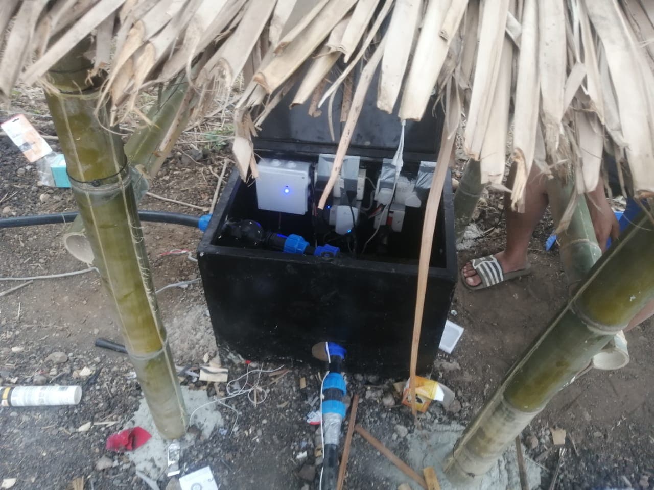
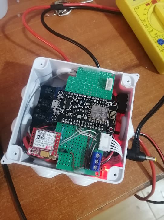
Hardware Development
I designed the PCB and soldred it in a perforated board.
Conclusion
The controller was initially deployed to serve an area of 1 acre, and it has been operational since 2020, which amounts to approximately 3 years at the time of writing. During this period, the controller has proven to be reliable and effective in automating the irrigation process for the designated area.
To accommodate the expansion of the irrigation system, a new module similar to the existing one was recently added. This addition aims to handle an additional 1 acre of land. The expectation is that the new module will maintain the same level of reliability and performance as the previous one.
Looking ahead, there are plans to enhance the controller's design and functionality by developing a printed circuit board (PCB). The goal is to create a modular system that is easy to replicate and deploy. By designing a PCB, it will be possible to standardize the controller's components and streamline the assembly process. This approach will facilitate scalability and simplify the development of future modules, allowing for efficient expansion of the irrigation system as needed.
The intention behind these efforts is to ensure the continued reliability and ease of replication of the irrigation controller, enabling its widespread adoption and use in various agricultural settings.